Tuesday, February 28, 2012

Wireless Reprogrammable PS2 Controller (Part III)

(or how I came to ditch veroboard)

img1s

Okay…

So, in the last post, I was about to build a vero-board model of the WRPC, having successfully demonstrated proof of concept on breadboard.

The reasons I chose veroboard for the next phase was that:

  1. There are a lot of pins on microcontrollers and my drill press isn’t compatible with the 0.8mm bit.
    (read that as: I don’t wanna hand-drill a billion holes)

  2. Less effort than a custom PCB

Point B became more than arguable over the course of development, as you’ll soon read about. For those of you either not on Google+ or just not reading what I post (fine, then!), here’s how the progress reports went:

Drama - Act 1, Scene 1

One fine day on Google+…
Later…
Finally…

Why did it fail?

The veroboard approach failed because either:

  1. I somehow made the tiniest little melt or jumper or something but because of how immensely complicated the back of the board became (because I wanted it to look nice), diagnosing it became impossible (but I still tried).

    OR

  2. Nothing was wrong with the veroboard, even though diagnosis was impossible. There was a mistake in the breadboard to veroboard conversion.

img2s

As it turns out…

When I finally caved and rebuilt the breadboard circuit with new parts (I will desolder and harvest the veroboard later), it did have an error. It didn’t make much sense to me at the time (and at time of writing, I’m just accepting it for now) but somehow connecting the second ground pin on the Atmega when pin 8 was already grounded caused an issue with reprogramming the board with the Wixel. If you’re interested, compare the schematic from the original post with the one below.

img3s

What I learned (VERO == UGLY)

Only use veroboard for circuits that will be out of sight or those that you don’t care how they look. If you try to get clever and reverse-wire a vero, it will only come back and bite you in the arse.

img5s

Onwards and Upwards

Once I threw out the vero idea, rebuilt the breadboard (and spent hours tracing down the source of the error), I was ready to arrange the PCB. After a few hours of rework, here’s the completed design courtesy of Fritzing:

img6s

Smaller than the vero model and much sexier.

I have included a full set of breakout header traces for both microprocessors and space for two stabilizing capacitors on the regulator, should I desire to add them.

Press-n-Peel

img7s

Now, the main reason I wanted to avoid a custom PCB for a prototype in the first place was because of all the dicking around with transferring a design to the board itself.

To that end (and because UV boards are bloody expensive), I bought some Press-n-Peel film from techniks.com. I have tried several different ways of PCB transfer, but I will have to say that provided you’re willing to do a bit of trial and error (like any method) with your printer settings, iron heat and method, Press-n-Peel film will give you the best PCB-making experience for your buck.

It took me 5 attempts to work out the correct combination of printer setting, iron heat and method but after those five attempts, I had this:

img8s

You’ll notice some minor touch ups because for this one (funnily enough) I used an imperfect piece of film. Murphy can eat my shorts as usual. Anyhow, it was only a short, soft scrub from that to this (custom type/art was added post-Fritzing in Inkscape, but more on that later):

img9s

And after all the etching and glazing…

img10s

…and all the drilling work (which I’m not that good at by hand) I realised…

img11s

…that I’d printed the bloody thing out BACKWARDS.

img12s

Well! Isn’t this just a full-on bag of …. F…un ….

Nevermind.

While it did massively increase the complexity of the soldering job (I soldered the microcontrollers on the reverse side) and changed the overall look of the finished board, I still managed to pull it off without losing it (somehow). I even held it together when my soldering iron died in the middle of it (I fixed it again).

The final (hardware) product

After this very very long and dramatic journey, with more twists and turns than I could even be bothered writing about (yes, there were more), here it is - the finished hardware:

img13s img14s img15s img16s img17s

Afterthoughts

I have written myself a reminder to do this, so I’ll get to it when I can spare another moment… I am going to post the settings that worked best for me with the Press-n-Peel film because I didn’t find that many articles that were very helpful about it online.

Until then…

Sunday, February 19, 2012

Wireless Reprogrammable PS2 Controller (Part II)

Standalone Migration

I’ve spent several hours over the weekend arranging the schematic and new Vero board version of the PS2 Controller project, as well as freeing it from the Arduino tether. The controller now functions completely standalone exactly as it did when hooked up to the Arduino.

There are many benefits of migrating to a standalone from an Arduino-based project.

Some of these are:

  1. Reduced project cost (chips and resonators are WAAAY cheaper than an entire Arduino board)
  2. Freeing up your Arduino for another project
  3. Reduced physical footprint

img1t

Vero and Schematic Diagrams

In the first post I promised that I would publish the schematic once I was happy with it and I’m making good on that. This is version 1.0 of the Wireless Reprogrammable PS2 controller in both Vero and Schematic forms.

img2t img3t

Next Steps

From here, I will be making the Vero version, assembling the controller as one unit and designing and implementing ABE’s menu system, so there are more posts to look forward to yet. :)

Saturday, February 18, 2012

Wireless Reprogrammable PS2 Controller (Part I and a half)

Intro

I’ve been writing a bit on the menu system I’m developing to get my design clear and optimised. I thought - Why not share it?

What follows is where I’m up to.

Outputs

The Robot Controller System (RCS) has an LCD screen of two lines, each having 16 character spaces of 5 x 8 pixels. Each character space is separated by 1-2 pixel sized gaps.

With this in mind, all displays and menus must be designed to fit comfortably in this space.

The system is also equipped with a piezo speaker for interface and other feedback.

Inputs

  • 2 x Left Buttons (top)
  • 2 x Right Buttons (top)
  • 1 x Analog D-Pad (Left, Right, Up, Down)
  • 1 x Select Button
  • 1 x Start Button
  • 4 x Action Buttons (Triangle, Circle, X, Square)
  • 2 x Analog Joysticks
  • 2 x Joystick Buttons

Menu Navigation

The menu navigation style will be reminiscent of PS2 menus.

  • Up and Down will change the selected menu item
  • X enters an item’s submenu or executes an item
  • Triangle exits a submenu or cancels execution of an item
  • Where possible, the menu will include human-helpful prompts
  • For menu items that involve editing values, the Left and Right buttons will move between characters and jump between fields if multiple exist
  • If an item is editable, it will be underlined or marked
  • Multi-character values will only be able to be edited one character at a time (i.e. no decimal rollover)
  • X will jump forward between fields until the last field and then it will act as a confirmation button
  • Triangle will jump backward until at the first field and then act as a cancellation button
  • Start will toggle “Settings” menu visibility
  • Select will toggle “Mode” menu visibility

Non-Menu Modes

When the RCS is not displaying menus, it will display a configurable HUD or other display relevant to the current “mode”.

These might include:

  • Distance to target
  • Battery levels
  • Directional heading
  • Temperature data
  • Speed
  • Control hints
  • Mode indication
  • Signal strength

And of course, if the current mode is interactive, feedback on the current controls or state of the controlled.

LCD Screen Guides

Note that '_' indicates variable area. If only one line is described, it indicates the top line unless otherwise noted.

  • LCD Layout
    ################
    ################
  • Setting Mode Layouts
    < __ASetting__ >
    012345ABCDEF
    ----------|-----
    On
  • Enumerated Mode Layout
    ____ASetting____
    < Option 12345 >
  • Action Mode Layout
    < ___Action___ >
    X=Go ^=Stop

Friday, February 17, 2012

Wireless Reprogrammable PS2 Controller (Part I)

Awesome Sauce Wixel & Arduino/Atmega Based PlayStation 2 Project Controller

pic1m
pic9s pic10s pic11s

The Reason

Ok, so I was at my girlfriend’s family’s place on some recent holiday and I was being asked to show off what my robot ABE could do. I did the fully automated things by turning him on and doing a few little pre-programmed responsive actions (covering his “eyes”, covering both IR sensors etc1) but I quickly realised that in order to show off his full bag of tricks, I would have to send him a few commands (or at least requests). At the time, the only way to do that was to take my other Wixel unit, plug it into my computer and send it some serial love. I had no computer setup there, nor my other Wixel.

The Design

At first I had intended to add two interrupt buttons to ABE and I even studied Schmitt circuitry to that end. Then, I had a better idea - I would add an infrared remote to him. While I was looking into that option, I had the best idea yet. Why should I waste even more power on extra components when ABE already has inbuilt wireless comms via the Wixel? Why don’t I just build a Wixel-enabled remote control?

The Better Design

To begin with, I ordered an LCD from Little Bird Electronics along with a few other parts for various new ideas. I had intended to use some old contact pads I had laying around for the buttons but I couldn’t come up with a design that I liked. It had to be light, portable and I had to want to use it.

After a bit of pondering, I remembered that I had an extra PS2 controller in a box doing nothing except tangling my other cabling up. Surely someone had already thought of this before? Google time!
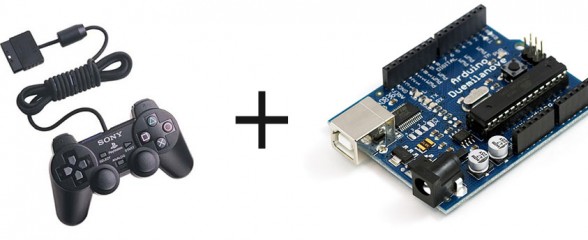
PS2 Plus Arduino?

Feasiblity Study

I looked around for an Arduino library to communicate with a PS2 controller and I found it right here. Thanks to Bill Porter, I had my answer. Not only was it possible but much of the work and testing was already done. Music to my ears, and a BIG thanks to Bill.

What I wanted

I wanted a compact, portable replacement for communicating with my robot via the Serial Monitor. This was my general requirements list:

It must…

  1. be compact and portable… (duh)
  2. allow multiple user inputs to the robot
  3. allow human-readable output from the robot
  4. look professional and slick so I will want to play with it (oooh shiny!)
  5. not interfere with the ability to wirelessly reprogram ABE

What I ended up making

I ended up making a comfortable, portable replacement for communicating with any of my projects that include a Wixel

It…

  1. is pretty compact and portable (at least hand-held) and is fairly light
  2. allows multiple user input to the robot via:
    • 10 digital buttons (all with changed, down and up event notifications)
    • 4 analog pressure-sensitive buttons
    • 2 biaxial analog stick controllers (with two additional digital buttons underneath them)
    • a microprocessor-driven LCD-Menu interface (that I’m writing AFTER this post)
  3. allows 32 5x8 pixel backlit LCD characters over 2 lines for human-readable output and interaction
  4. looks professional (the Sony part… my bit looks nice enough :)
  5. allows pass-through reprogramming of ABE when the controller is plugged into a USB port using the standard Arduino IDE

Sweet - I’ve totally decimated my requirements list (that’s a good thing)!

Oh, and as an added “I wonder if I can….” bonus, I’ve also managed to design it in such a way that if ABE is plugged into the computer USB port, the controller itself can be wirelessly reprogrammed (without having to remove the chip). Woot!

What does that mean?

Well, it means I can remote control ABE and any other project that I’m making that includes a Wixel.

It means I can make stand-alone programs for the controller (and I have a few sneaky projects in mind) and its 2.4GHz transceiver (Wixel) - I could even theoretically reprogram ABE in-the-field.

It means - I’ve made myself a new toy to play with. :)

pic14m pic6m

The LCD Bracket

To make a slick-looking controller, you’ve got to have slick-looking curves. Because I still have a fair bit of the stuff and because it’s durable, mouldable (if you’re really careful with a blowtorch or hot air machine) and strong, I decided on using more perspex. I wanted the bracket to tilt the LCD screen slightly towards the user (me) for good visibility and comfort. I also wanted not to mess up the beautiful aesthetics of Sony’s controller.

I scribbled up the design (above) on my whiteboard one afternoon and measured it carefully onto a piece a day or so later. To cut it, I used a fine-grade hacksaw and to sculpt it, I used a pocket blowtorch (very carefully) and a padded vice. I beveled the edges afterwards with some hand-files and wet-and-dry.

Bracket Parts List
  • 3mm x 6mm (M3) Screws
  • 10mm Hex Spacers
  • 90mm x 3mm x 120mm Sheet of Perspex

pic7m pic8m

After I’d drilled all the bracket holes, I also drilled holes in the PS2 controller’s lower shell. I had to be extremely careful to keep my M3 screwheads away from the interior circuitry but there was enough clearance for them to co-exist peacefully. Holes in the perspex were threaded using an M3 tap tool, so no extra nuts were needed (keeps the minimalist aesthetic).

pic2m

PS2 Controller Wiring

The wire pinout provided at Bill’s site was a little different from the one I had, but it was noted that the colours were succeptable to frequent change.

pic3m

Bill’s Site Pin/Wire layout:
  1. Brown = data
  2. Orange = command out
  3. Grey = dualshock power
  4. Black = ground
  5. Red = power
  6. Yellow = attention
  7. Blue = clock
  8. White = ?
  9. Green = ack
My Pin/Wire layout:
  1. Brown = data
  2. Orange = command out
  3. Purple = dualshock power
  4. Black, Grey (both) = ground
  5. Pink = power
  6. Yellow = attention
  7. Blue = clock
  8. N/C (shield and bare wire also both N/C)
  9. Green = ack

pic4m

PS2 + Arduino

In order to link up the PS2 controller to the Arduino, I needed Bill Porter’s library called PS2X.

Download PS2X from Github

Once I had wired it all up as explained in the very top of the code (see the breadboard diagram below for the cheatsheet), I turned it on but it didn’t seem to work straight away.

Not to worry!

Bill has an absolutely brilliant section on his site that’s dedicated to troubleshooting the library. What a guy!

Bill’s Brilliant Troubleshooting Guide

It turned out that all I needed was a single resistor to act as a pullup for the controller. Simple as that.

pic5m

PS2 + Arduino + LCD

After I’d linked up the controller to the Arduino (and yes, mucked about with it for a good half-hour), I added in the LCD. This was probably the easiest part. The wiring is only 4 pins (power, ground, SCL, SDA) and the sample code in the DFRobot-provided library gave me all I needed to find-and-replace all of the Serial.print calls in Bill’s demo with lcd.print.

Download the DFRobot LCD Library for Arduino from DFRobot

…more fiddling and mucking about ensued…

pic12m

PS2 + Arduino + LCD + Wixel

For the home stretch (a few days later - I’m a busy guy), I added the Wixel into the mix. The following links came very much in handy:

For this part, (ABE has a Wixel Shield) I wanted the circuit to function similarly to the Wixel Shield. That way, I would be able to program both ABE and the controller remotely and still allow full communication between the two (without buying or powering more hardware). What followed was a simple (remember, this is version 1.0) design that was mostly voltage dividers2 and pullup resistors.

pic13

The Circuit

I’m going to write this in point form so that it reads simply. It’s not that complex a circuit, though. Here’s how it works:

  1. The Arduino powers everything from its 5V pin
  2. All grounds are connected (as they should be)
  3. The PS2 controller pins (shown on board left to right, pin1 to pin8) connect to Arduino digital pins, power and ground
    (pins 3 and 8 are not connected)
  4. The LCD pins connect to the I2C bus (SCL,SDA), power and ground
  5. The Wixel takes its power directly from the Arduino 5V pin (it has its own regulator)
  6. Arduino Transmission (TX) lines are voltage-divided down to about 3.3V for the Wixel’s RX inputs
  7. The Wixel Transmission (TX) lines are connected directly to the Arduino (because 3.3V is still considered HIGH by 5V logic)
  8. Various pullup resistors were required to keep the Arduino/Wixel logic in certain states at certain times (especially during program-loading)
  9. The single transistor is part of a quick on-board digital inverter (NOT gate). When the Wixel wants to reset the Arduino (when programming), it sets P0_0 to HIGH. However, to reset the Arduino, the RESET pin has to be pulled LOW. This is a very simplified version of the connection shown on the Wixel Shield schematic (but it works well).

N.B. I can’t remember if I put the right resistance values into Fritzing before I generated the breadboard graphic.

Stay tuned for the next post. I’ll add a schematic with values and details of the next steps, and if required, I’ll post some more explanation about the inverter, pullup resistors and logic conversion. By then, I should have some code to post too.


  • ABE is (at the time of writing) programmed to start in different "modes" depending on the condition of some of his sensors at time of startup. If an object of greater than 31°C is less than 10cm away from his sonar sensors (i.e. a human hand over his eyes), he will start up in standby mode. If both of his IR sensors detect obstacles on startup, he will start to sing a tune.

  • The Wixel runs at 3.3V whereas the Arduino runs at 5V. I bought a logic converter for the job but it was actually simpler to construct the circuit from basic components as I have.

  • Wednesday, February 8, 2012

    Damned Discounts

    Damn. Whenever announces discount codes when there are parts that I want, I end up trawling their site for over an hour when I could be earning the cash to pay for it! I guess it’s going to be a late night tonight. Here’s what I just grabbed….

    • 1x I2C EEPROM - 256kbit
    • 1x Breakout Board for SD-MMC Cards
    • 1x I2C/TWI LCD1602 Module
    • 1x Flexiforce Pressure Sensor - 25lbs.
    • 1x Compass Module - HMC6352
    • 7x Arduino Stackable Header Kit

    If you can’t already tell, I have some new projects in the works as well as expansion of some existing projects.

    More details coming soon…

    The Burn & Go

    (From brainspace to prototype in a couple of hours…)

    Burn & Go Burn & Go meets Arduino Burn & Go with Arduino (tail showing) Quick and dirty breadboarding

    What is it?

    The Burn & Go is a semi-shield for Arduino. It acts as a zero-insertion-force pass-through adapter for the 28-pin Atmel chip.

    What does it do?

    It has two modes, one for each state of the “tail” switch. They are:

    1. Go mode
      Complete pass-through. There is literally no difference in this mode between having the Burn & Go attached and having the Atmel chip inserted directly. Sketches can be uploaded and all inputs and outputs of the chip can be used as normal.

    2. Burn mode
      Optiloader mode. When this mode is entered with a chip locked into the Zippy socket, the chip will be loaded with the Optiboot bootloader that corresponds to the chip type. For compatible chips, see the listing below.

    How do you use it?

    • You flip the switch one way, the bootloader is burned (you don’t even have to disconnect it from the computer or whatever it’s doing at the time) and a green light flashes (red if there’s a problem)

    • Flip the switch the other way, the Arduino functions entirely as normal (it will be a clean sketch-slate if it’s just been in the other position with the power on)

    How does it work (the short, short version)?

    The two-way switch extends power and ground from the Arduino to the onboard Atmel chip (with Optiloader on it). It also moves the reset control from the Arduino board to the onboard chip.

    So in position one, everything is as normal because the onboard chip has no power and no ground, so the connections to its digital pins are irrelevant (open). In position two, we move the reset control away from the Arduino board (and the hair-trigger watchdog circuit) and give power and ground to the onboard chip.

    In position one, it’s like the extra circuitry doesn’t exist (all power and ground connections are tied to the switch) and in position two, only the onboard circuit is in full control (wired up very similar to the way one Arduino can be used to program another - see the references below).

    Why did you make it?

    I wanted a no-fuss integrated method that would allow me to take a blank Atmel chip (which are more expensive if you buy them with a bootloader), burn the bootloader and then proceed to load it with a sketch. I also wanted a way to ensure that with the many projects that I had in mind, I wouldn’t end up bending pins so often when moving the Atmels around.

    What are the benefits of it?

    Well, it… :

    • … can detect and burn the appropriate bootloader for your blank Atmel chip in mere seconds (see the list of compatible chips below)
    • … can protect your pins if you are intending to do a lot of chip swapping (like for standalone project development)
    • … eliminates the need for a seperate bootloader and sketch programmer (and the need to move the chip at all in the process)
    • … fits on the Arduino UNO without obstructing any pins (but I will have to invent some high headers OR make it into a full shield if I wish to put shields on it)
    • … reduces standalone project costs and times by allowing the fast use of entirely blank Atmel chips and at the flick of a switch, allowing them to be loaded with sketches too
    • … doesn’t need to be connected to a computer or set up in any way (except powered) to burn a boot loader
    • … is powered entirely by the Arduino itself
    • … does not require disabling of the Arduino’s auto-reset feature and hence the UNO works fine with this
    • … doesn’t affect the completely normal functioning of your Arduino so it can stay attached at all times

    Any down sides?

    • It currently obstructs some of the onboard LEDs (I will eventually either redesign the board to be smaller or make pass-through LEDs for it)
    • It currently uses header pins to connect with the Arduino DIP socket so it makes them irrepairably larger, however this can be rectified by using a DIP socket to do this instead
    • It currently can only be used without shields, as it requires header extensions (due to the height of the Zippy socket)

    Parts & Tools List

    1. 1 x Vero-style protoboard (cut to 50mm x 40mm)
    2. 2 x 3mm LED (I used red and green)
    3. 1 x 16MHz Ceramic Resonator (but any Atmel-compatible value can be used - up to 20MHz)
    4. 1 x 10KOhm Resistor (for the reset pulldown)
    5. 1 x 100Ohm Resistor (for the LEDs)
    6. 1 x 28-pin Zippy Socket
    7. 2 x 14-pin DIP Sockets (they form the 28 pin socket for the on-board Atmel328P)
    8. 1 x Atmel328P (loaded with a custom derivative of the very excellent Optiloader sketch - more details below)
    9. 1 x 2-Way 3 or 4 contacts switch (isolated contacts)
    10. A few lengths of proto-wire
    11. Heatshrink tubing of various sizes
    12. Solder (and flux for tinning)
    13. Soldering Iron
    14. Hacksaw or Dremel
    15. Stanley knife (very sharp, for trace cutting)
    16. Arduino UNO (with Atmel chip)
    17. Either 28 standard header pins in two strips of 14 or two more lots of 14-pin DIP Sockets

    Reference Information

    • Optiloader @ github - This project would be nothing without this awesome sketch by Bill Westfield (“WestfW”). The only changes I needed to make to his sketch were pin and notification related (so that LEDs do certain things when successful or failed). The sketch includes the hex-encoded Optiboot (Arduino UNO) boatloaders for the following chips:
      • Atmega328P
      • Atmega328
      • Atmega168
      • Atmega8
    • The Arduino UNO schematic - this came in handy when devising the circuit (I have R1 and R3)
    • Arduino To Breadboard - how to use your Arduino to program an Atmel chip on a breadboard
    • Building an Arduino on a Breadboard - this article I found after making the Burn & Go but it seems like a useful resource

    Downloadable Content

    I didn’t bother running this through a schematic or designer first. As the caption above says, I did it straight from head to breadboard. Later on I might do a retrospective one if there’s enough interest. This is, however, only the first revision. I may also do another revision in future that does away with the switch in favour of transistor or opto-coupled switching, but this was the quickest and easiest method.

    Disclaimer

    I’ve probably made an ommission or error in this post. Bite me. :) No, seriously, if there’s a mistake or oversight by all means contact me and I’ll make the correction. I try to be as thorough as possible but sometimes I just don’t have time to double check everything. I could do better, I’m sure, but I’d rather be playing with toys.

    Monday, February 6, 2012

    ABE

    In the beginning (of 2012), there was ABE…

    Earlier this year, I brought to life a small, cutish robotic creation called ABE. ABE stands for Autonomous Base Explorer (or something like that). It’s a working title. Here are some pictures of ABE with indications of what his parts are and what he (yes, he) can do. I’ll add more detail later (perhaps).

    Chips & Boards Servo Motors Sensors & Outputs Power & Stability

    Robot Definition Statement

    A mobile, terrestrial, wirelessly programmable and interactive, human-interactive expandable robot prototype with multiple sensory inputs and feedback devices, capable of self-navigation and autonomous task completion. (bloated, I know)

    Current Working Title

    ABE = Autonomous Base/Building Explorer

    What Can He Do?

    ABE can do quite a number of things. Based on the Arduino UNO, he has a highly flexible programmable microprocessor. Apart from that, there’s the other sensors and capabilities. Here’s a short list:

    He Can…

    1. Measure distance from himself to an object in centimeters using sonar
      • Measurements are in centimeters
      • The sonar sensor (SRF05) is mounted in the pan and tilt sensor array
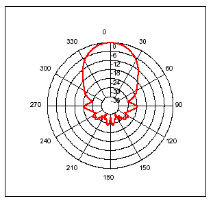
      • The beam pattern is shown here:
        Beam Pattern
      • Sensor supplier’s information
    2. Measure the temperature in a 90 degree field of view
      • Operating ambient temperature is between -40 and 85 degrees Celcius
      • Measurement temperatures range from -70 to 382.2 degrees Celcius
      • Measurement resolution is 0.02 degrees Celcius
      • Measurement accuracy is +/- 0.5 degrees Celcius at Room Temperature
      • It is immune to IR & Sunlight
      • The Infrared Temperature sensor is mounted in the pan and tilt sensor array
      • Sensor Datasheet
    3. Detect obstacles using front left and right mounted IR proximity sensors
      • Measurements are only the existence or not of an obstacle
      • Sensors are angled to allow approximately 7cm forward detection and enough sidewards detection to allow approximately 1-2cm clearence for the wheels.
    4. Pan and tilt the sonar and temperature sensor
      • The pan range is approximately 180 degrees, with 90 degrees being full forward
      • The tilt range is less than 180 degrees, with 45 degrees being level, 120 degrees being up and rear facing and a minimum tilt of about 10-20 degrees
    5. Indicate the direction of sensing for sonar and temperature using a low power laser
      • The laser is mounted on the pan and tilt array to allow him to indicate the direction of the sonar and temperature sensor
      • The laser can be turned on and off
    6. Play simple tunes using the front-mounted piezo
      • Currently, he plays Edna’s theme from The Day Of The Tentacle by LucasArts
      • Of course, this is most useful for human feedback
    7. Sense knock patterns on the front of the bot using the piezo
      • This is untested but completely plausible (it would require the piezo also be connected to an analog input as it is not currently so connected)
    8. Convey information to humans using a green 7-segment display
      • Currently, this is used to show the current mode of the robot, it being programmed for multiple modes of use. Future plans are to have a debounced microswitch mode button on the bot itself
    9. Move itself around using two continuous rotation servos and a third caster contact point
      • Wheels are rubber
      • Caster is ¾" plastic ballbearing caster, located at the bot’s rear
    10. Operate without being connected to any non-mobile power source
      • On-board batteries are 9v and 6v (latter for the servo power)
    11. Communicate with a computer or other electronic device by means of a Wixel wireless serial link
      • Presently, this is used to provide feedback to the developer and to provide instruction to the robot
      • Future plans are to change the interface to use PHP and serproxy instead of the standard Arduino IDE serial monitor
    12. Be completely reprogrammed at any time over-the-air using the Wixel wireless serial link
      • This is limited by the range of the pair of Wixels, which is about 12 meters
      • The Wixels themselves must first be programmed when connected locally (only needed to be done once)
      • Programming may be battery intensive